

Product Parameters
|
Item |
Specification |
|
Blanking Size |
1.5T x 436W x 210P |
|
Material Utilization Rate |
67.2% |
|
Tooling Size |
3650L x 900W x 750H mm |
|
Press Tonnage |
Main: PKZY800 / Backup: 630T |
|
Shut Height |
800 mm |
|
Feeding Height |
410 mm - 640 mm |
|
Lower Lifting Height |
50 mm |
|
Cutting Force |
128T |
|
Forming Force |
170T |
|
Stripper Force |
27.9T |
|
Total Force |
325.9T |

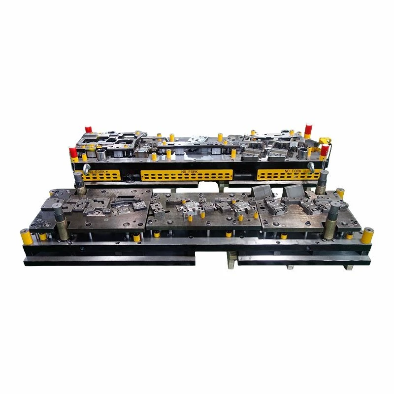
Progressive Die Tooling should be developed from a confirmed strip proposal and press interface. The progressive tool design drawing needs to show the 210 mm pitch, strip width, feed direction, plate stack, die height, lifting points, sensors, and die clamping areas. A 67.2% material utilization rate is useful for costing, but the carrier must still remain strong after early piercing. In progression tooling, carrier bridges are functional elements; reducing them without checking strip stiffness can cause pitch drift, tipping, or poor pilot entry.
The listed 128 T cutting force, 170 T forming force, and 27.9 T stripper force should be reviewed by station, not only as a 325.9 T total. Progressive tool design calculations also consider off-center loading, spring force, press energy, and the timing of high-load stations. CAE simulation may be used where material flow, thinning, or springback cannot be judged reliably from geometry alone. Some customer specifications describe the assembly as a progressive tool in press tool production. If the same tool is transferred between the PKZY800 main press and a 630 T backup press, shut height, bolster size, feed height, and available stroke must all be confirmed.
The Progressive Die Tooling tryout should produce a labeled strip with samples retained from critical stations. Inspectors check pitch, hole position, trimming line, profile, burr height, bend angle, and tool marks before approving a speed increase. A progressive sheet metal stamping tool also needs stable strip lifting and controlled dropping off at the last station. The stated 50 mm lower lifting height and 410-640 mm feeding range should be verified on the actual press setup. Scrap chutes must clear the bolster and should not allow long waste pieces to bridge.
Technical Credentials for Progressive Tooling
Progressive die tooling requires coordinated control of strip guidance, pilots, station loads, lifters, sensors, and final separation. The certificate area can present ISO 9001, automotive quality-system records where applicable, export operation qualification, high-tech enterprise recognition, and patents associated with continuous processing or integrated die mechanisms.
This module gives the customer an evidence-based view of the supplier behind the Progressive Die Tooling. It is useful before final design release because it shows that technical calculations, CAE review, press matching, trial-strip inspection, and document control can be supported by a formal management system.


FAQ
Hot Tags: progressive die tooling, China progressive die tooling manufacturers, suppliers, factory


