

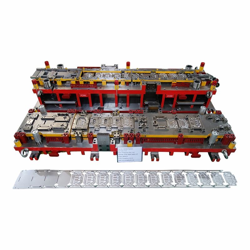
Appliance Stamping Die for Large Cover Progressive Forming
This Appliance Stamping Die was developed for a Bosch cover project using a 1-out progressive process. The completed tool measures 2870 × 840 × 660 mm and weighs approximately 4.6T.
A cover part brings a different set of priorities from a hidden bracket. Broad surfaces can show waviness, scratches or local tool marks very easily, while the outer profile and mounting features still need to fit the final appliance assembly. The strip layout therefore has to control both geometry and surface condition as the part moves through the die.
For this Appliance Stamping Die, tryout is not judged only by whether the part can be formed. Flatness, visible surfaces, edge condition, hole location, feeding behavior and final part dropping off are checked together before the tool is prepared for production handover.

Product Parameters
|
Item |
Specification |
|
Product Name |
Appliance Stamping Die |
|
Part Type |
Cover |
|
Tool Type |
Progressive Die |
|
Output |
1 Out |
|
Tooling Size |
2870L × 840W × 660H mm |
|
Tool Weight |
Approx. 4.6T |
Why This Cover Tool Needs Different Attention
Large cover surfaces make local waviness and tool marks easier to see. Contact areas are checked during tryout instead of relying only on final dimensional results.
The 2870 mm tool length and 4.6T weight require suitable machining, assembly, lifting and press setup. Changdong supports tooling up to approximately 4 meters.
The press line includes 800T, 400T, 260T, three 160T presses and one 45T press. Feeders are available for relevant progressive die trials.
Large die plates and working areas can be machined on the 3-meter gantry CNC, supported by WEDM, drilling, assembly and tryout in the same facility.

Progressive strip showing how the cover develops while remaining supported through the forming sequence.
The Strip Has to Protect the Cover as Well as Carry It
The strip has to remain stiff enough to carry a relatively broad part through later stations. If carrier support is removed too early, the cover can twist or move during feeding and the final flatness becomes harder to control.
Material utilization is important, but an unstable carrier can cost more in tryout and production than the saved strip width.
A cover may slide across working surfaces as it develops. Contact direction, insert finish, lubrication and local pressure can influence whether scratches or drag marks appear.
The Appliance Stamping Die is therefore checked for surface pickup as well as profile and dimensional accuracy.
A mounting hole may be easy to pierce early but move after a later forming operation. Features used for appliance assembly are placed in the sequence according to how stable their surrounding geometry is at that point.
What We Check on a Cover During Tryout
Large flat or shallow-formed areas can look acceptable at first glance while the outer edge still carries local waviness. The cover is checked on a stable reference surface so profile and edge condition can be separated from simple part rocking.
Surface marks are traced back to the station where they first appear. This avoids polishing or modifying later stations that only receive an already damaged surface.
Mounting holes, folded edges and other assembly features are checked against the drawing datum rather than only against nearby stamped geometry. This matters when the cover has to match another housing or bracket during final assembly.
Outer edges and pierced areas are checked for burr direction and cutting condition. A cover that passes its overall dimensions can still create assembly or handling problems if the edge condition is poor.
Production Details That Are Easy to Miss During Sample Approval
A qualified cover can still be scratched after forming if part dropping off is unstable. The discharge path is checked so the finished surface does not strike the tool, chute or scrap during removal.
Trim scrap and pierced slugs need a clean route away from the working area. Accumulated scrap can create unexpected surface damage or interfere with later strokes even when the forming stations themselves are correct.
Feeding is checked with the tool rather than treated as a separate machine setting. Strip entry, pilot engagement and carrier movement have to remain repeatable as the cycling rate is increased.
Maintenance Is Easier When Wear Areas Are Planned Early
High-wear cutting edges or local forming areas can be separated into replaceable inserts where the design allows. This keeps later repair focused on the working component instead of a larger die plate.
TD or other suitable coating options can be reviewed for selected working areas when wear or galling justifies additional surface treatment. The decision depends on base steel, hardness, contact pressure and lubrication.
MISUMI components are commonly used. PUNCH INDUSTRY, SANKYO OILLESS, Danly, Dayton or FIBRO can also be considered when the customer's die standard and component dimensions permit substitution.
Completed Tool Before Handover

Completed 1-out progressive die. Tool size: 2870 × 840 × 660 mm; approximate weight: 4.6T.
Lifting positions, die clamping and maintenance access need to be considered as part of the finished tool. These details become important every time the die is installed, removed or serviced.
After the dimensions and appearance are corrected, the Appliance Stamping Die is checked through repeated operation. Feeding, part discharge and scrap movement need to stay controlled rather than producing one good part under carefully adjusted conditions.
The final sample is submitted after the agreed dimensional and appearance items have passed. For a cover part, this can include both measurement results and visible-surface requirements.
What to Send for a Cover Tooling Review
For a new Appliance Stamping Die project, send the dimensioned 2D drawing, matching 3D model, die technical standards and target press specification.
For cover parts, surface requirements are particularly important. Please identify which faces are visible, where scratches or tool marks are restricted, and whether the material is coated, pre-painted or requires later surface treatment.
EAU, assembly-critical dimensions, required sample quantity, packing requirements and the target delivery schedule are also useful. These details allow the tooling route to be reviewed around the real appearance and production requirements of the cover.
Useful RFQ Data
• 2D drawing
• 3D CAD / STEP model
• Material and thickness
• Visible-surface definition
• Surface / coating requirements
• Die technical standards
• Press specification
• Assembly-critical dimensions
• EAU
• Packing requirements
FAQ
Hot Tags: appliance stamping die, China appliance stamping die manufacturers, suppliers, factory, custom bending dies, custom compound metal stamping die, custom piercing die, custom single stage stamping die, precision custom metal stamping die, precision sheet metal stamping die


