

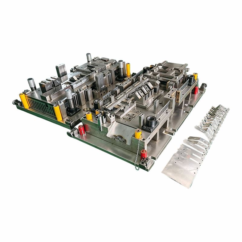
Stamping Die for 2-Out Rear Subframe Bracket Production
This Stamping Die is a two-out progressive tool for a rear subframe mudguard bracket made from 0.8 mm DC01 coil.
The finished die is 1600L × 870W × 500H mm and weighs 2232 kg. Project data lists a 540 mm shut height, an 88 mm progression and three possible press capacities: 200T, 250T and 400T.
Two parts leave the die every stroke. That makes the project less about producing "twice as many parts" and more about keeping both outputs under the same running condition. Feed position, cutting condition, part separation and discharge are compared across the two outputs during tryout.

Product Parameters
|
Item |
Specification |
|
Product Name |
Stamping Die |
|
Application |
Rear Subframe Mudguard Bracket |
|
Die No. |
SA2FC-5301915 |
|
Tooling Type |
Progressive Die |
|
Part Material |
DC01 |
|
Thickness |
0.8 mm |
|
Tooling Size |
1600L × 870W × 500H mm |
|
Tool Weight |
2232 kg |
|
Shut Height |
540 mm |
|
Parts per Stroke |
2 |
|
Listed Press Options |
200T / 250T / 400T |
|
Blanking Size |
252W × 88P mm |
|
Feed Material |
Coil |
The Two Outputs Are Compared, Not Assumed Equal
The strip has to arrive in a repeatable position across its full width. During tryout, pilot entry and carrier condition are watched from both outputs. If one side consistently arrives differently, the team does not wait for the finished brackets to reveal the problem.
Punch wear or clearance does not always develop identically on both sides. Burr direction and edge condition are therefore compared between the two stamped parts rather than represented by one sample only.
The last operation has to release both parts without one bracket catching, rebounding or interfering with the other. A two-out Stamping Die needs two reliable part-out conditions in every stroke.
Which Press Should Run the Die?
The project information lists three press capacities. Final press assignment still has to match the actual force requirement, available energy, stroke and production speed.
Bolster size and clamping matter too. A 1600 × 870 mm tool has to sit correctly on the selected press instead of simply fitting between the columns.
The shut-height reference affects how the tool is installed and adjusted. It needs to be checked together with press adjustment range, feeder position and the actual closed-tool condition.
The 88 mm progression only works consistently when the coil enters the die at the correct height and direction. A feeder setting that looks correct by itself can still create strip drag if the die entrance is poorly aligned.
T0 Focus for This Bracket Tool
Hole position, bend condition and local profile are checked after the part is released from the die. This is the condition that will actually enter the subframe assembly process.
With 0.8 mm DC01, trim and pierce condition can change quickly if cutting clearance or punch condition is wrong. Burrs are checked before the tool is run faster.
The material has to leave the punches and rise cleanly after each stroke. Excessive strip lift or drag can disturb the next 88 mm feed even when the stamped part itself still looks acceptable.
The two finished brackets are compared during the same trial run. This gives the team a direct way to identify side-to-side differences before normal production begins.
Where Scrap Goes Matters on This Tool
Flat offcuts and slugs can stack inside the lower tool. Scrap openings are therefore checked with the real waste shape during tryout instead of relying only on clearance shown in CAD.
Part dropping off is kept separate from scrap discharge. The finished edges should not slide across sharp scrap or collide with the second stamped part.
Embossed sheet can provide a smoother sliding surface. Where flat scrap repeatedly bridges, a pneumatic cylinder-driven vibrator may be used to keep the discharge moving.
A 2232 kg Die Has to Be Easy to Handle More Than Once
The tool will be installed, removed and serviced many times after delivery. Lifting points and clamping access are therefore considered for repeated use, not only for shipping.
Common punches, die buttons and local inserts are easier to service when replacement does not require opening unrelated areas of the Stamping Die.
After a punch or insert is serviced, the tool needs a practical reference for returning that component to the approved production condition.
Closed Tool After Tryout
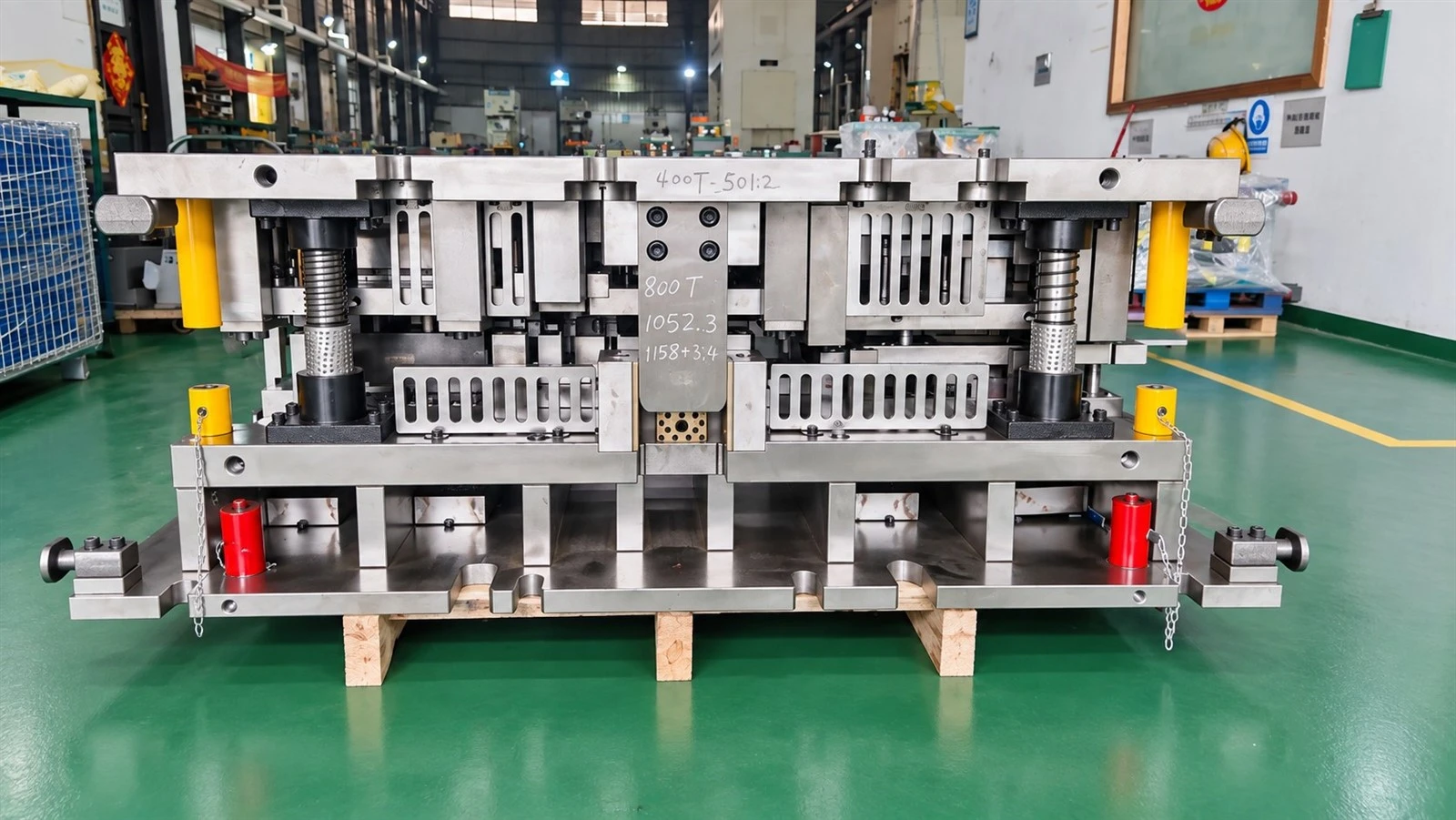
Completed progressive die: 1600 × 870 × 500 mm, 2232 kg.
Tool Build and Qualification Behind the Project
Dongguan Changdong Tool & Die Co., Ltd. was founded in 2012 and operates an approximately 4,000 m² tooling facility in Dongguan.
Tool design, CNC machining, WEDM, EDM, drilling, fitting, assembly and press tryout are coordinated within the same tooling operation. The factory has six WEDM machines and press capacity up to 800T, with feeder equipment available for coil-fed tooling trials.
The high-tech enterprise qualification shown here adds company-level background to the physical project evidence. It reflects ongoing engineering and tooling-development activity, while the actual Stamping Die, its tryout result and approved samples remain the direct evidence for this project.

The most useful starting package is the released 2D and 3D part data, target press information, die technical standards, material specification and sample approval criteria. With those items, Changdong can review the two-out strip concept, press fit and project timing against the actual production conditions.
Hot Tags: stamping die, China stamping die manufacturers, suppliers, factory, application specific stamping dies, custom bending dies, custom piercing die, custom transfer metal stamping dies, precision custom metal stamping die, precision stamping die


