
Stamping Tool for LH/RH Rear Floor Connecting Plates
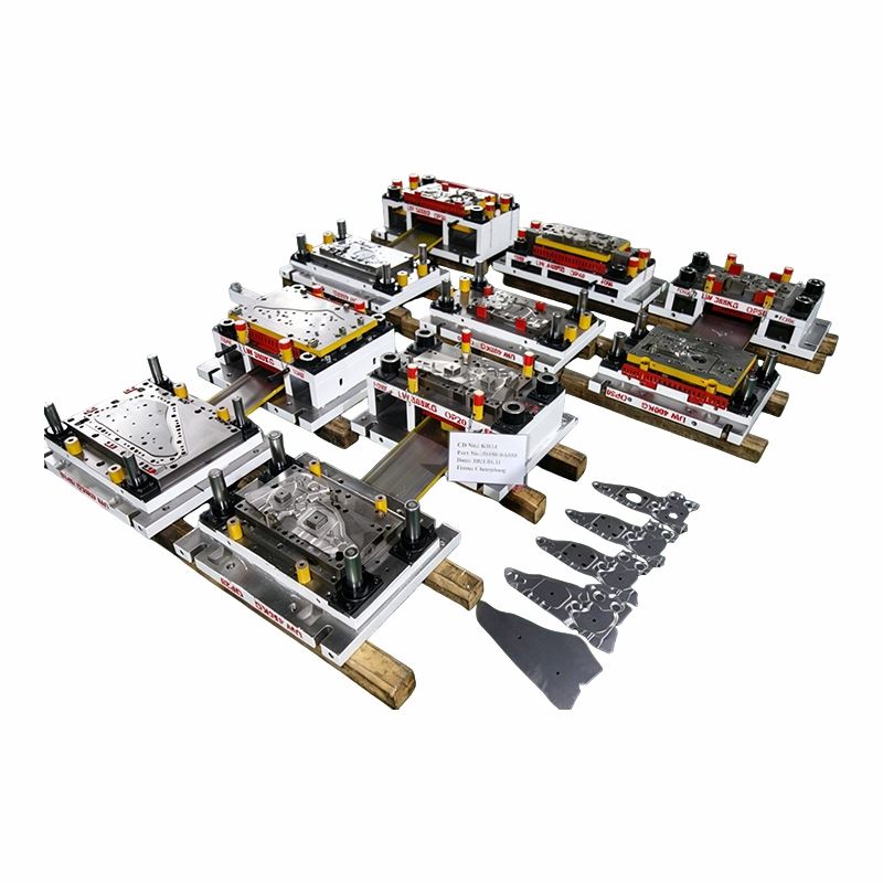
This Stamping Tool project consists of five single-stage dies from OP10 to OP50 for rear floor lower cross-member LH/RH connecting plates. The specified material is 1.4 mm 340/590DPD+Z high-strength coated steel.
The left- and right-hand parts belong to the same assembly area, but they should not be treated as automatically identical. Mounting holes, flanges, weld-related features and local geometry are checked against the drawing for each side.
The five-tool route gives Changdong room to control the part step by step while keeping the body-assembly datums visible through the process. The final objective is not simply a stamped component that matches a standalone measurement report, but a part that fits the rear-floor cross-member interface as intended.

Product Parameters
|
Item |
Specification |
|
Product Name |
Stamping Tool |
|
Application |
Rear Floor Lower Cross Member LH/RH Connecting Plates |
|
Tooling Route |
OP10 / OP20 / OP30 / OP40 / OP50 |
|
Tool Type |
5 Single-Stage Dies |
|
Part Material |
340/590DPD+Z |
|
Thickness |
1.4 mm |
LH and RH: Similar Parts Are Not Automatically the Same
Where LH and RH geometry is genuinely mirrored, forming and inspection methods can follow a common approach. This can simplify design review and make troubleshooting easier.
A locator, pierced hole, flange or trim edge is still checked against its own released drawing. A correction made for one side is not copied blindly to the other side just because the parts look similar.
The useful references are the datums that control how the plate fits the rear-floor structure. Tooling correction should preserve those references through OP10–OP50.

OP10–OP50 process samples used to compare geometry, flange condition and joining features through the five single-stage operations.
Why the Intermediate Samples Matter for Body Fit
A final hole-position problem does not always begin at the piercing operation. If a flange opens after forming or the local profile moves after springback, the hole can shift relative to the body datum even though the punch itself is correctly positioned.
By comparing the samples between operations, the team can see whether the geometry changed before or after a joining feature was created.
Welding and Fastening Features Need Stable Surrounding Geometry
Rear-floor connecting plates commonly work as part of a larger welded or fastened structure. The surrounding surface, flange and hole relationship therefore matters more than one isolated dimension.
The Stamping Tool correction is judged against that relationship, not only against the nearest edge of the stamped part.
340/590DPD+Z: The Released Shape Is What Counts
High-strength sheet can recover after the forming load is removed. A flange that is correct while constrained may open after the part is released, so the free-state sample is the useful reference for correction.
A secondary forming correction may be useful for flange angle or local profile, but it should have a defined target. Extra forming operations are not added simply because the material is high strength.
Contact areas are kept smooth so repeated forming does not create unnecessary pickup, coating damage or tool marks. Surface condition is checked together with the dimensional result.
Five Separate Dies Make Maintenance More Selective
If one trim insert or punch reaches its service limit, the maintenance work stays with that die instead of automatically opening the full OP10–OP50 set.
Trim steels, piercing components and local high-wear forming inserts can be made replaceable where the design allows. This keeps repair focused on the part that actually wears.
Lifting points, die clamping and service areas are documented by OP. That becomes useful when the five tools are handled independently on the production floor.
How the Five-Tool Job Moves Through Changdong
The five tools do not need to sit in one manufacturing queue. Plates for one die can be under CNC machining while inserts from another tool are on WEDM and a third die has already entered fitting.
Changdong has six WEDM machines, CNC equipment, a 3-meter gantry CNC and high-speed drilling. This gives the workshop room to move several OP tools forward at the same time.
Engineering remains connected to the shop floor throughout the build. The company has 13 die design engineers using CATIA, AutoForm, Dynaform and VISI, with technical discussions handled directly when tooling changes are required.
For a five-die Stamping Tool program, that matters because one drawing revision can affect more than one operation. Changes need to reach the correct tool before machining or fitting moves too far ahead.
Changdong In-House Capability
• 13 die design engineers
• CATIA / AutoForm / Dynaform / VISI
• 6 WEDM machines
• 3 m gantry CNC
• High-speed drilling
• Presses from 45T to 800T
• Approx. 4,000 m² factory
Tryout Is Tied to Body-Assembly Features
The flange is checked in its released condition because springback can move the outer edge and change the body-fit relationship.
Welding or fastening holes are measured against the relevant assembly datums. LH and RH results are evaluated against their own drawings rather than assumed to be identical.
Profile variation near a mounting or joining area can affect fit even when the surrounding outline remains acceptable. Those local areas receive more attention during correction.
Coating damage, scratches, trimming condition and burr direction are reviewed where they can influence handling, welding or final assembly.
Completed OP10–OP50 Stamping Tool Set

Five completed single-stage dies for the LH/RH rear floor connecting-plate project.
What the Approved Set Should Preserve
The final reference is the relationship between the five dies and the assembly features they create. Flange condition, joining-hole position and local profile should remain understandable by OP after the tools enter production.
If a later sample moves after wear or insert replacement, the earlier process samples provide a useful comparison point instead of forcing maintenance to diagnose the five-tool route from the finished part alone.
Side-Specific Changes Stay Documented
Where LH and RH details differ, the approved correction belongs to the relevant side. This prevents a future service change from being copied across both parts without measurement.
That distinction is important for a Stamping Tool project whose parts share an assembly area but do not necessarily share every feature.
Hot Tags: stamping tool, China stamping tool manufacturers, suppliers, factory, application specific stamping dies, custom compound metal stamping die, custom forming dies, custom piercing die, custom single stage stamping die, precision custom metal stamping die


