

Drawing Package Scope
The Progressive Die Drawing normally includes the strip layout, die assembly, upper and lower plans, section views, plate details, insert drawings, standard-part references, sensor positions, and a bill of materials. The die drawing process also needs a clear datum system, tolerance strategy, steel and heat-treatment notes, and revision identification. Drawings should be detailed enough for CNC machining, WEDM, EDM, grinding, die clamping, and inspection without relying on verbal instructions that can be lost during the project.
Station and Press Information
A second purpose of the Progressive Die Drawing is to explain the working sequence. Each station should identify piercing, forming, idle, restrike, trimming, and cut-off operations, along with pilot entry, carrier condition, lifter travel, and dropping off. Press specification data such as feed direction, shut height, bolster size, tonnage, and feed line should be shown where it affects the design. Scrap chutes, sensors, and maintenance access must be coordinated with the plate stack.

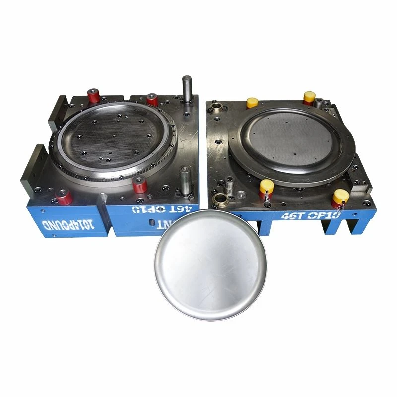
Tooling terminology can be confusing. Drawings for tube drawing dies focus on reducing or sizing a tube through a die, while a drawing die set for sheet forming controls material flow into a cavity. Drawing die components may include a punch, die ring, binder, draw beads, and pressure system. A sheet metal drawing die is therefore different from a progressive-tool drawing, although a progressive sequence can contain a shallow drawing or forming station. The documentation should state which process is actually intended.
Before design starts, check the intended press specification against the customer's die technical standards. The controlled 2D drawing and latest 3D drawing should carry the same revision. Material data, annual volume, part tolerances, inspection standards, and preferred component brands belong in the release record. Revision changes must identify affected stations and parts so machining and tryout teams work from the same issue. A change log should also state whether existing steel can be modified or whether a replacement insert is required.
Design Documentation and Patent Credentials
Progressive die drawing work should be supported by controlled design procedures, revision management, and technical evidence for station layout, strip guidance, sensor positions, and final part discharge. The certificate area can present ISO 9001, high-tech enterprise recognition, export operation qualification, and patents related to continuous feeding, multi-station die structures, or progressive-strip processing devices.
For this Progressive Die Drawing page, the module shows that drawing output is backed by a formal quality and engineering system. It helps buyers assess whether strip layout, die assembly drawings, BOM control, machining details, and tryout correction records can remain consistent from design release through tool maintenance.


Hot Tags: progressive die drawing, China progressive die drawing manufacturers, suppliers, factory


